
A structural model arrives from another project team.
The file opens. The building is visible. Columns, beams, slabs and walls appear where expected. The model can be rotated, reviewed and federated with other disciplines. From a distance, the digital handover appears complete.
Then the structural engineer begins preparing the analytical model.
Member axes require adjustment. Supports have to be recreated. End releases are missing or uncertain. Material descriptions cannot be mapped confidently to calculation properties. Loads remain in spreadsheets. Load combinations are buried in calculation notes. Local coordinate systems must be checked manually.
Within hours, the engineer is rebuilding information that the project believes it has already exchanged.
This is often called a software problem. It is not.
The software has opened the file and displayed what it received. The deeper failure occurred earlier, when nobody defined what the receiving engineer needed, who was responsible for providing it or how its quality would be verified.
BIM does not usually fail at the software layer. It fails at the handover between business requirements, engineering judgement and structured information.
 Technology underperforms when the organisation’s direction and information requirements are misaligned.
A visible model can hide an incomplete handover
Construction organisations have invested heavily in modelling platforms, common data environments, coordination software and digital dashboards. These systems generate an enormous volume of information.
Yet volume is not continuity.
A model created for spatial coordination may not contain what is needed for structural analysis. A model suitable for drawing production may not support asset management. A geometrically correct object may still lack the classification, performance data or relationship required by the next participant.
This distinction is frequently overlooked because geometry creates confidence. When a building appears correctly on screen, people assume the information has travelled with it.
Seeing a beam is not the same as understanding its analytical role. Seeing a wall does not reveal its boundary conditions. Recognising a section name does not guarantee that the receiving system can interpret its properties.
The handover has transferred a representation of the building. It has not necessarily transferred the meaning required for the next decision.
Engineers rebuild models because uncertainty is expensive
A physical building model and a structural analysis model describe the same project for different purposes.
The physical model represents objects intended to be designed, coordinated, procured and constructed. A beam has volume. A wall has thickness. A slab contains openings and edges.
The analytical model is an engineering abstraction. A beam becomes a curve between nodes. It requires a cross-section, material, orientation, eccentricity and end conditions. A slab may become an analytical surface with a defined thickness and modelling assumptions. Connections must be interpreted as rigid, pinned, released or partially restrained. Loads require magnitudes, directions, cases and combinations.
Converting the first model into the second is not a clerical file operation. It includes engineering decisions.
The engineer must reuse what can be trusted and verify or create what requires professional judgement. When the exchange does not distinguish between those categories, rebuilding becomes the rational response.
Interoperability is a management responsibility
Interoperability is commonly treated as a software-procurement feature: does the platform support IFC, connect to the common data environment or integrate with the analysis package?
Those questions matter, but they come too late. Software cannot determine what the organisation has not defined.
Before selecting an exchange method, a project must establish:
- the purpose of the exchange;
- the decisions it must support;
- the minimum information required;
- the party responsible for each field;
- the method of verification;
- the treatment of missing or uncertain values;
- the procedure for managing changes;
- the traceability required between systems.
These are questions of governance, accountability and delivery design. A software licence cannot answer them.
IFC is more capable than many IFC exchanges
Industry Foundation Classes is often described as a neutral format for model coordination. That description is incomplete.
IFC 4.3 includes a structural-analysis domain for analytical members, connections, supports, loads, load cases, load combinations and some analysis results. It can also express relationships between physical elements and their analytical idealisations. buildingSMART’s documentation describes curve and surface members, boundary conditions and structural actions.
The schema can carry significant engineering information. That does not mean every IFC file contains it.
A valid exchange may include physical beams without analytical members, geometry without supports or material names without properties suitable for analysis. It may omit load cases because the export was designed for coordination rather than calculation.
“Delivered in IFC” is therefore not a meaningful performance measure by itself. The relevant measure is whether the exchange contains the agreed information for its intended use.
Looking at the schemas, not claiming a software test
Without the relevant authoring and analysis applications, claiming to have tested an automated IFC-to-SAF workflow would be misleading. A more defensible investigation is to examine the public data structures themselves.
The comparison uses buildingSMART’s public structural-analysis IFC example and the official Structural Analysis Format examples.
This is not a conversion benchmark. It asks a narrower question: how does each format organise the engineering information that a converter would have to understand?
| Engineering concept | IFC representation | SAF representation |
|---|---|---|
| Analysis model | IfcStructuralAnalysisModel | Project and model sheets |
| Analytical node | IfcStructuralPointConnection | StructuralPointConnection |
| Beam or column | IfcStructuralCurveMember | StructuralCurveMember |
| Material | IFC material entities and relationships | StructuralMaterial |
| Cross-section | IFC profile definitions and profile sets | StructuralCrossSection |
| Support | Structural connection and boundary condition | StructuralPointSupport |
| Load case | IfcStructuralLoadCase | StructuralLoadCase |
| Member load | Structural action and load entities | Structural action tables |
IFC is a broad relational model. Understanding one analytical member may require following references to geometry, profile, material, physical element, connections, boundary conditions and applied actions.
SAF is narrower. It organises structural-analysis information through spreadsheet tables, with relationships maintained through names and references between sheets.
In simple terms, IFC behaves like a connected information network. SAF behaves like a structured engineering workbook.
Neither is inherently superior. They serve different operational purposes.
Mapping is not copying
Moving information between IFC and SAF requires decisions about identifiers, geometry, local axes, material and profile naming, supports, releases, load cases, combinations and units.
Some mappings may be direct. Others require transformation. A curve member with a section reference may transfer predictably. A physical beam with no analytical counterpart cannot. A support represented through several IFC entities may need to become one SAF row.
This is why interoperability cannot be reduced to file compatibility. A receiving system needs rules for interpretation, and the project needs a method for deciding whether those interpretations are acceptable.
The business risk is hidden in reconstruction
Rebuilding a model may appear to be a technical inconvenience. Across a portfolio, it becomes an operating cost:
- additional engineering hours;
- delayed reviews;
- duplicated quality checks;
- transcription risk;
- weaker traceability;
- inconsistent assumptions;
- dependence on individual experience.
These costs rarely return to the original exchange. They appear later as coordination time, analysis preparation, rework or unexplained delay.
A credible BIM return-on-investment assessment must therefore look beyond model production. It should measure what the model prevents the next participant from rebuilding.
Requirements must become testable
The objective is not maximum information. It is sufficient, reliable information for a defined purpose.
The Information Delivery Specification, or IDS, is a buildingSMART standard for expressing IFC information requirements in a computer-interpretable form. It can check agreed entities, attributes, classifications, properties, materials and relationships. The official IDS repository contains the schema and implementation guidance.
IDS cannot decide whether a structural assumption is correct. It cannot determine whether a connection should be pinned or rigid. It can determine whether required information was supplied in the agreed structure.
Professional judgement evaluates the decision. Automated validation checks the delivery.
A practical operating model
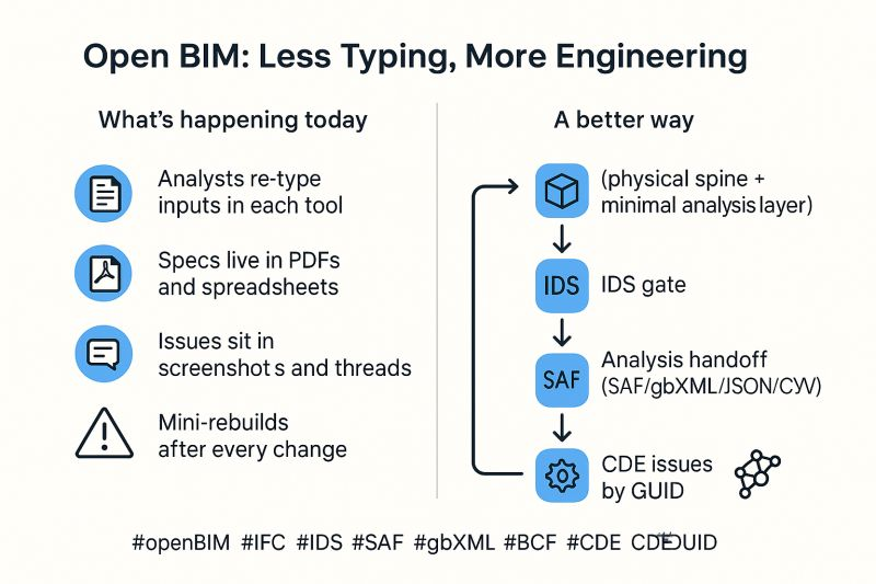
A dependable exchange requires a controlled chain:
- Define the intended use.
- Specify the minimum information.
- Assign ownership.
- Validate before exchange.
- Map transparently.
- Report what was missing, transformed, derived or ignored.
- Preserve engineering control over analytical assumptions.
- Maintain traceability between physical objects, analytical objects, issues and decisions.
 Reliable information delivery is a managed feedback loop, not a one-time export.
This is not a technology strategy in isolation. It is an information-management operating model supported by technology.
BIM succeeds when the next person can use the information
Construction does not suffer from a shortage of files. It produces models, drawings, schedules, specifications, calculations, photographs, issue logs and asset registers in enormous quantities.
The problem is that information is frequently created for one immediate task and loses structure when responsibility changes hands.
BIM does not fail because the industry lacks sufficiently advanced platforms. It fails when organisations procure technology before defining information requirements, ownership, validation and handover responsibilities.
The software layer can only process the operating model it is given. When that operating model is unclear, software does not create alignment. It exposes the absence of it.
Construction already has enough data. The next stage of digital maturity is making that data dependable when responsibility changes hands.